Saturday, April 11, 2009

Some Progress to Report


Spent a good part of the day and night in the garage. Got the following done, some with pictures.

1. Mocked up the fan in the chassis with the mock-up block and my intake and generator. Did this mostly for kicks while I was waiting for some advice from my uncle before proceeding with installing the pilot bushing in the flywheel. No pics, but I was able to spin the fan and see it clears by 3/4" at a minimum, and I can center it in the radiator or raise or lower depending upon what I need; plenty of room.


2a. Oakie-honed the clutch release bushings, because they were too tight for the clutch release shaft to rotate easily. Did this by wrapping emory cloth around an undersized shaft (brass drift punch) and spun it in the bushings. Kept checking the shaft until she rotated easily. Reassembled the release shaft and fork, with a bolt and nut, instead of the peened-over pin from the factory. (The bushings are the golden colored bands (bronze?) supporting either end of the shaft; you can barely see the edge of them in the photo.)


2b. Filed the square head on the drain plug, so I can remove it with my "universal" Ford wrench from Vern Tardel. It fit the fill plug, but not the drain plug, so what to do? File it until it fits! (I shot and posted the pic at top of the gears because I'm not sure I ever posted one when I installed the new (to me) cluster gear and low-reverse slider gear months ago.)

3. Mocked up the front shocks with another pair of Ford F-1 pickup truck front shock mounts. These were already bent to be lower by leaning forward. I already have a stock set, but they stand pretty tall. My friend let me borrow these to see how they'd fit. I like the way they look, but not certain how they'll fit around the headlight stands I'm considering. Once mounted this way, though, I had some interference with the castellated nuts on the spring shackle (see second photo).


4. Finally installed the pilot bushing (the bronze bushing in the center of the flywheel). Can't recall if I wrote last week that I polished the flywheel and pressure plate, but you can see that in the photo below, too.


Won't get out to the garage tomorrow, as it's Easter, so church in the morning, and family "brunch" in the afternoon.

-30-

Monday, April 6, 2009

Oil Pan Fix Pt. 1

Unremarkable title tonight. Too bushed from work to be creative. The day job, that is. Good news is I have so much vacation time I'm required to use by the end of the fiscal year that I'm taking every Friday off (alternating with my 9-80 Fridays off) through July 4th weekend. Yeah. "Hot Rod Boot Camp," as my GF says.

Here's the quick update, with just a couple pictures. More coming later. Forgot to take the "after" pictures when the pan was out in the sun. Had beautiful weather last weekend, so dragged the oil pan out and cleaned it up (the little residual oil and sludge that was in it) with some Gunk Engine Brite and Off Oven Cleaner (hey, whatever does the trick). Don't ask where the runoff went.

Here's the hole Pick-n-Pull punched in it to drain the oil. Hard to tell scale here, but I can easily fit the end of my pinkie finger in there.


After cleaning the pan, I proceeded to very clumsily pry and pound away at the puncture with a combination of screwdriver, awl, and eventually pick hammers and a heavy body spoon. Did a halfway decent job of cleaning up the metal and flattening it out from the inside. Next, I'll break out the torch and try to relearn brazing to close up the hole. Will probably practice on some junk metal first, to get the hang of it, then just go for it.

-30-

Tuesday, March 24, 2009

A Forgotten Update

Whoops, I forgot to post my most recent modest bit of work from Saturday (didn't go hiking, but didn't really get to spend a lot of time in the garage, either). No excuses, just didn't get a lot done, BUT did primer and paint the timing cover the correct "Antique Ford Green" according to the aerosol can. Oh well, small steps.


Also, forgot last week when posting the engine stand photos to include the photos below of a valve lifter remover tool I got somewhere sometime (vague, huh; yeah, just can't remember). All sorts of variants of these things from the era, but thought you'd enjoy seeing another one. Sorry for the somewhat blurry photos; just using my iPhone - it's the only digital camera I've got.

Also pictured is a Plomb (yeah, I spelled that right) valve lifter tool. Plomb is the predecessor to Proto. You can learn more here and here. I love my Plomb tools. Have a bunch from various places, including my bro-in-law's grandfather, who was a tank and heavy machinery mechanic. Haven't spent a lot of time hunting down more to complete my collection or build a period-correct tool kit for the hot rod, but it crosses my mind on occasion. When I'm ready, here's the place to troll for them.


Looking forward to my upcoming three day weekend. My girlfriend will be out of town visiting her folks, so I'll be spending the weekend with my fickle mistress Twice Lucky.

-30-

Thursday, March 19, 2009

Metal Has a Memory


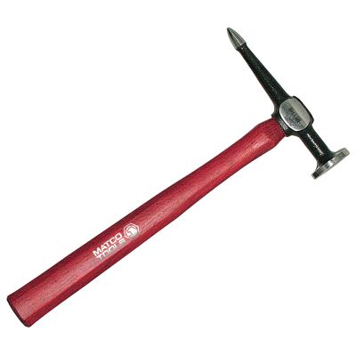
Tonight I spent a couple hours in the garage. Got a late start, but no matter. Decided I'd straighten the double pulley I got some time ago, as it was bent up a little upon removal. I've always been afraid to beat on sheet metal with the collection of body hammers and dollies I have, but just kept my uncle's words in mind tonight as I pinged away on the pulley: metal has a memory.

And it does. Alas, I neglected to take "before" pictures, but these pulleys were bent outward in a couple places. In the photo above, I began with a pick, and moved to a ball pean hammer, starting at the initial "impact" of the dent and worked it out. While somewhat slightly dimpled afterward, the major dent itself is gone.

For the work below, I just found a curved-face body hammer in my toolbox and proceeded to tap on the outside edge of the pulley; lightly at first, then with greater force and confidence until, after repeated checking against a straight edge and then a piece of steel plate, I'd straightened them out! (The slightly shiny edge in each photo shows where I worked on them)


While I'm sure it would be possible to go too far, or tap too much and go past where you should, generally the metal (in the case of body panels and such) is stamped at such a ridiculously high pressure, the metal retains a memory of it, so using the hammer and dolly just brings it back into shape.

I first learned this from my uncle from stories his mentor told him, and demonstrated, by pounding a fender out on the front lawn with a mallet! I used this advice to pound back into shape a pair of 1929 license plates, followed by a pair of 1926 plates, using just a rubber mallet and a floor mat on the concrete floor of my garage. To my amazement, after pounding and flipping the plate back and forth, it straightened right out until I had what appeared to be matching pairs of freshly stamped metal; and that made me a believer.

After tonight's little bit (and I mean little) of sheet metal work, I got out the timing cover and distributor parts for kicks and started assembling them. As you can see from the picture, I have my bead blasted timing cover, recently rebuilt distributor, and NOS (new old stock) rotor and cap (with the Ford tags still on them!) ready for assembly. Also found and wire-brushed the proper shoulder bolts to mount the distributor.


If the weather is inclement Saturday, I may be back out in the garage again. If not, then I'll be hiking.

-30-

Monday, March 16, 2009

K.R. Wilson Engine Stand (Finally)

OK, so let me lead off by saying 1) I don't believe this is really a K.R. Wilson flathead engine stand, and 2) this won't be that comprehensive of a post, but conclude by saying 3) if you've gotten here by a Google search (and I know I get a lot of hits from that search string), you'll soon find - if you haven't already - that for some reason there just doesn't seem to be a lot on the 'net about these things, and seemingly fewer pictures. So therefore, I've tried to shoot some pictures of mine, and throw in a few links for good measure. Oh, and the color's not original. The original was a darker (purpler?) red; I painted this one with several cans of International Harvester Implement Red paint from the local Ace Hardware.

I welcome comments if you have any info on my stand and its attachments, or have any other good references on these things, or simply have something to contribute to the conversation. Thanks in advance!

So I first mentioned my engine stand back in this post. However, since that time, I've been meaning to get some additional photos taken and posted to help you see what these things look like, along with a few of the attachments, which maybe you can identify, 'cause I sure can't.

The Stand (and its crazy locking "feet")


The ratchet/position lock (for lack of a better name; you can see here how mine differs from the KRW model, seen in the links at the end of this post)


The mounting plate. As I stated in my original post, I got the plate from Vern Tardel, then had my friend the welding instructor and his students cut down some heavy wall pipe and weld it to the plate.


The engine lift block; cast iron and mounts in the lifter valley. You can buy this brand new from Specialty Ford Parts in Rosemead, CA (doin' it old school: no website)


Can be positioned to balance just the motor, or the motor and transmission. (I stamped the indicators in mine)


And now, the other accessories:


Mystery Attachment 1. Made for KRW as you can tell by the "cog" end. It's incredibly heavy cast iron and stamped with the Ford oval and labeled "T54L 6005C USE WITH T52 T6005 CJD OR KJD" and "K.R. Wilson 6005" (I believe 6005X is the number for the engine stand). A local car museum has one of these in its "shop" display, but does not identify it.


Mystery Attachment 2. With "cog" end as Attachment 1. It's cast aluminum and stamped "FO-MO-CO T54L-6005-E"


Mystery Attachment 3. Might be shop-made, but fabricated to fit my engine stand. No markings. Heavy plate steel semi-regularly drilled; welded to a keyed shaft that fits the "cog" on my stand.


Mystery Attachment 4. Fits on the shaft to which I have the motor mount attached. No markings. Simple curved steel tube with flat plate ends.


Here are some other K.R. Wilson engine stand links:
Check out these posts (one) (this one's great), (two) and (three) on the HAMB, if ya haven't already - great meeting place for the traditional rod and kustom guys and gals.

A few folks (one) and (two) out there have K.R. Wilson tool catalog reprints for sale. I've never bought one since they're all pre-war, so the accessories I have are unlikely to be in them as I believe they're post-flathead era.

Well, that about wraps it up for this post. Again, if you've got any feedback, I encourage you to comment below. Thanks!

-30-